Analysis of the Sloshing of a Large Tank with Fukushima Daiichi Seismic Excitations
The Westinghouse AP1000 nuclear reactor design is a pressurized water reactor with a power rating of 3415 MWt and an electrical output of at least 1000 MWe. The AP1000 design contains a variety of engineering and operational improvements providing additional safety margins and addresses the U.S. NRC severe accident, safety goal, and standardization policy statements. The most significant improvement of the AP1000 with respect to the previous generation is the use of safety systems that employ passive means such as gravity, natural circulation, condensation and evaporation, and stored energy for accident mitigation. These passive safety systems perform safety injection, residual heat removal, and containment cooling functions. Additional safety features of the AP1000 include a larger pressurizer, an in-containment refuelling water storage tank, automatic depressurization system, digital main control room, hermetically-sealed canned reactor coolant pump motors mounted to the steam generator, and increased battery capacity. In addition, the facility is designed for a 60-year life.
The AP1000 design provides for multiple levels of defense for accident mitigation (defense-in-depth), resulting in extremely low core damage probabilities while minimizing the occurrences of containment flooding, pressurization, and heat-up. Defense-in-depth is integral to the AP1000 design, with a multitude of individual plant features capable of providing some degree of defense of plant safety.
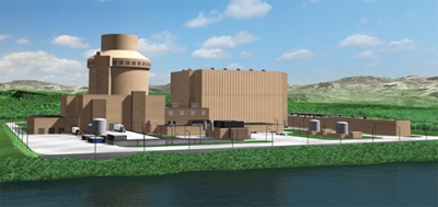
Fig. 1 - Assembly (rear view)
Six aspects of the AP1000 design contribute to defensein- depth:
- Stable Operation. In normal operation, the most fundamental level of defense-in-depth ensures that the plant can be operated stably and reliably.
- Physical Plant Boundaries. One of the most recognizable aspects of defense-in-depth is the protection of public safety through the physical plant boundaries. Releases of radiation are directly prevented by the fuel cladding, the reactor pressure boundary, and the containment pressure boundary.
- Passive Safety-Related Systems. The AP1000 safetyrelated passive systems and equipment are sufficient to automatically establish and maintain core cooling and containment integrity for an indefinite period of time following design basis events assuming the most limiting single failure, no operator action and no onsite and offsite ac power sources.
- Diversity within the Safety-Related Systems. An additional level of defense is provided through the diverse mitigation functions within the passive safetyrelated systems. This diversity exists, for example, in the residual heat removal function. The Passive Residual Heat Remover Exchanger (PRHR HX) is the passive safety-related feature for removing decay heat during a transient. In case of multiple failures in the Passive Residual Heat Remover Exchanger,defense-indepth is provided by the passive safety injection and automatic depressurization (passive feed and bleed) functions of the passive core cooling system.
- Non-safety Systems. The next level of defense-in-depth is the availability of certain non-safety systems for reducing the potential for events leading to core damage. For more probable events, these highly reliable non-safety systems automatically actuate to provide a first level of defense to reduce the likelihood of unnecessary actuation and operation of the safetyrelated systems.
- Containing Core Damage. The AP1000 design provides the operators with the ability to drain the IRWST water into the reactor cavity in the event that the core has uncovered and is melting. This prevents reactor vessel failure and subsequent relocation of molten core debris into the containment. Retention of the debris in the vessel significantly reduces the uncertainty in the assessment of containment failure and radioactive release to the environment due to ex-vessel severe accident phenomena.
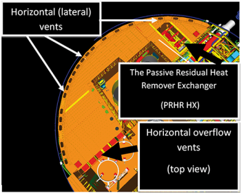
Fig. 2 - Physical layout of the horizontal (lateral) and
horizontal overflow vents, of the Passive Residual Heat
Remover Exchanger (PRHR HX).
Last but not least, the AP1000 is designed with environmental consideration as a priority. The safety of the public, the power plant workers, and the impact to the environment have been carefully integrated in the design and construction of the plant.
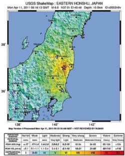
Fig.3 - Location of the Eastern Honshu Earthquake
Objectives of the Analysis
The accident at the Fukushima Daiichi nuclear power plant in Japan has triggered the need for an immediate and
coordinated response from the EU, aimed at identifying potential further improvements, in line with the fundamental
principle of the continuous improvement of nuclear safety. In addition to the EU-mandated stress tests, ANSALDO
NUCLEARE SpA has decided to perform an evaluation of the response of the In-containment Refueling Water Storage Tank (a
key component of the Westinghouse AP1000 nuclear reactor) against the water sloshing induced by a Fukushima-Daiichi
class seismic excitation.
The objectives of the analysis are to evaluate:
- The objectives of the analysis are to evaluate:
- The post-excitation functionality of the Passive Residual Heat Remover Exchanger (PRHR HX, see The Geometry). Specifically, the key question is whether the Passive Residual Heat Remover Exchanger (PRHR HX), will continue to be fully immersed in the water (therefore not impacting the thermal balance and functionality of the device itself).
- The volume of water leaving/remaining in the In-containment Refueling Water Storage Tank (IRWST, see The Geometry) and the post-excitation level of water. • Frequency, amplitude and position of the water wave.
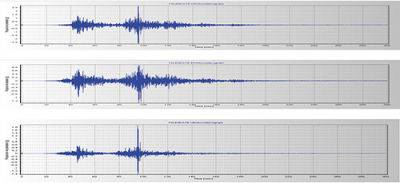
Fig.4 - Seismic excitations of the Fukushima earthquake
The analysis has been performed via two mainstream CFD codes: ANSYS/CFX5 and ANSYS/FLUENT. A specific geometry and mesh was created for these codes of the In-containment Refueling Water Storage Tank and the same seismic excitation was applied.
The Geometry
The In-containment Refueling Water Storage Tank (IRWST)
The In-containment Refueling Water Storage Tank (IRWST) is a very large concrete pool filled with cold borated
water. The main geometric features of the IRWST are:
- Floor Surface Area: in the range of 250 m2
- Water Volume: in the range of 2100 m3
- Water Height: in the range of 9 m
In nominal conditions, the distance between the water level and the ceiling is in the range of 0.5 m. Vents are provided to discharge steam and water through the roof of the IRWST to the containment. These vents must pass sufficient steam and water to prevent overpressurization of the IRWST during operation of the spargers (see Fig. 1). These vents are normally closed and open with a slight overpressure. Once these vents are opened they do not need to automatically reclose. Water discharged with steam through the vents to the containment must not drain back into the IRWST through the vents in order to prevent interference with the venting. Vents are provided to allow air/steam to enter the IRWST from the containment. These vents must pass sufficient air and steam to prevent excessive external pressurization of the IRWST during steam line breaks/LOCAs. These vents are normally closed and must open with a slight external pressure. Overflows are provided which discharge from the side wall of the IRWST into the refueling cavity. These overflows are normally closed and open with a slight overpressure. The general lay-out of the IRWST is shown in Fig. 1. Fig. 2 shows specific details of the IRWST.
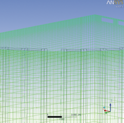
Fig.5 - Detailed view of the mesh at the corner
of the IRWST. The vents on the right side of the IRWST
are overlooking the Refueling Pit. Note the refinement
of the mesh in the upper part.
The Passive Residual Heat Remover Exchanger (PRHR HX)
The Passive Residual Heat Remover Exchanger (PRHR HX) is located within the steel containment vessel. The heat
exchanger is contained in the IRWST, which provides the heat sink for the heat exchanger. The heat exchanger consists
of a bank of C-tubes, connected at the top (inlet) and bottom (outlet) to a tube-sheet and channel head mounted on the
IRWST wall. The PRHR HX is connected to the Reactor Cooling System through an inlet line from one of the Reactor
Cooling System's hot leg. The outlet line connects to the associated steam generator cold leg plenum. The water in
the HX is stagnant and will be in thermal equilibrium with the water in the IRWST. This arrangement maintains a thermal
driving head during normal plant standby conditions which provides for the initial PRHR HX startup operation. The heat
exchanger is elevated above the Reactor Cooling System loops to induce natural circulation flow through the heat
exchanger when the reactor coolant pumps are not available. The PRHR heat exchanger piping arrangement also allows
actuation of the heat exchanger with reactor coolant pumps operating.
The seismic excitations
This analysis will use the seismic excitations (acceleration history, i.e. the acceleration in the 3 coordinate
directions Up/Down, East/West, North/South as a function of time) of the Eastern Honshu earthquake. The earthquake and
tsunami hit Japan on April 11, 2012 with M 6.6 (Fig. 3). The following three chart (Fig. 4) shows the seismic
excitations in term of acceleration time history of the earthquake. The three charts refers to the 3 coordinate
directions North/South, East/West, Up/Down. Please note the different scale.
The mesh
The pre-processors of the two applications (ANSYS/FLUENT and ANSYS/CFX5) have been used to generate a mesh
modeling the geometry for the IRWST. The mesh has been created from CAD models. Meshing density is linked to expected
regions of high gradient in the simulated field. The solution domain was subdivided in a lower part (the bottom of the
IRWST) where a coarser mesh was used and an upper part (close to the free surface) where a finer mesh was used to
better capture:
a) the amount of water leaving the IRWST through the vents (horizontal and lateral);
b) the shape and position of the wave induced by the sloshing.
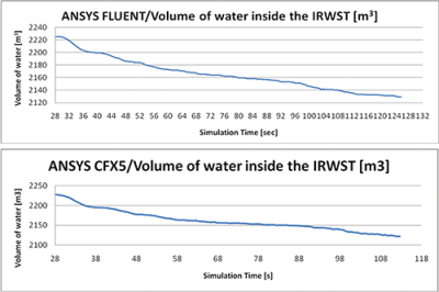
Fig 6 and 7 - Volume of water inside the IRWST as a function of time
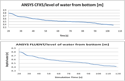
Fig 8 and 9 - Level of water inside the IRWST as a function of time
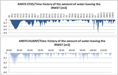
Fig 10 and 11 - Time history of the water leaving the IRWST
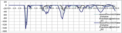
Fig 10a - Close-up view of the amount of water leaving the
IRWST via selected vents (time has been rescaled).
Extreme care was used to make sure that there would not be any disconnection or incorrect matching of boundary conditions between the two regions (i.e. the lower region and the upper region) because of the different meshing density. The number of cells for ANSYS/FLUENT is 896,724, the number of elements for the ANSYS/CFX5 is 735,540. Because of the different meshing techniques (element vs cell) and because of the different way for assigning the boundary and initial conditions between ANSYS/FLUENT and ANSYS/CFX5, the number of cells and the number of elements are not exactly the same. This difference does not have any significant impact on the modeling of the flow field as well as on the assessment of the volume of water leaving the IRWST because of the sloshing. Also, the different meshes makes for a marginally different value for the volume of water inside the IRWST at the beginning of the simulation (i.e. at t=0.0 s).
Results
The simulation has been performed using two well known and established applications each using a separate
methods: the Free Surface method via ANSYS CFX5 and the Volume of Fluid method via ANSYS FLUENT. The results are
therefore not biased by the selections of a specific method. Because of the low content of energy in the first 28
seconds of the acceleration time history, it was decided to begin the simulation from the 28th second, therefore the
results shown in this report will begin from 28 seconds.
The following set of results will be shown as a function of time:
- Fig. 6 and 7: volume of water inside the IRWST
- Fig. 8 and 9: level of water inside the IRWST
- Fig. 10 and 11: time history of the water leaving the IRWST
- Fig. 10a: a close-up view of the amount of water leaving the IRWST via selected vents
- Fig. 12 and 13: position of the water level at selected moments
- Fig. 14: adimensionalized sloshing-induced loads on the outer wall of the IRWST
Conclusions
The analysis of sloshing in the IRWST induced by a major earthquake shows that there will not be a significant
amount of water leaving the tank and that components key to ensure a continuous removal of heat will continue to be
completely immersed and operative in the tank (IRWST). While the surface wave hits several times the peripheral walls,
the roof and the PRHR HX, the pressures exerted on these components are well below the maximum design loads, therefore
the sloshing is not posing any beyonddesign loads to the named components. The position, height and evolution of the
surface wave are matched fairly well by the two applications. The two applications and numerical methods used for this
analysis yield similar albeit slightly different results, and they can be safely be used as an engineering design
simulation tools.
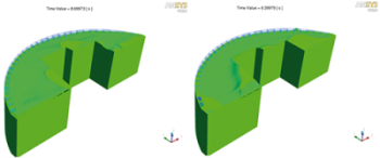
Fig 12 and 13 - Position of the water wave at selected
moments in or around the area of the PRHR HX
(ANSYS/CFX, time has been rescaled).
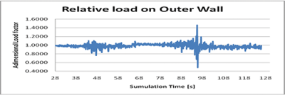
Fig 14 - Relative load on the Peripheral Outer Wall of the IRWST.
The load is the overall force acting on the whole wall.